Table of Contents
GPIO
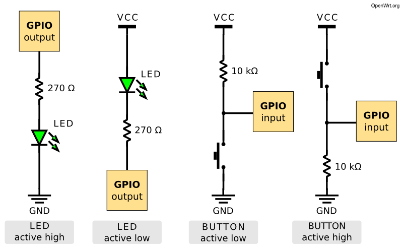
Basics

Pin define
 image taken from bpi-r2 schematics
| Sparefunction | Mainfunction | pin# | xxxxxxxxxxxxxxxxxxxxx | pin# | Mainfunction | Sparefunction |
|---|---|---|---|---|---|---|
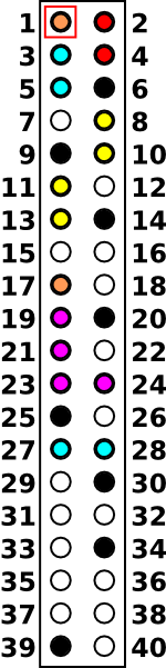 | ||||||
| - | 3V3 | 1 | 2 | 5V | - | |
| I2C_SDA0 | GPIO 75 | 3 | 4 | 5V | - | |
| I2C SCL0 | GPIO 76 | 5 | 6 | GND | - | |
| PWM3 | GPIO 206 | 7 | 8 | GPIO 82 | UART1 TX | |
| - | GND | 9 | 10 | GPIO 81 | UART1 RX | |
| UART0 TX | GPIO 80 | 11 | 12 | UCTS1 / INT2 | GPIO 24 (*) | |
| UART0 RX | GPIO 79 | 13 | 14 | GND | - | |
| PWM2 | GPIO 205 | 15 | 16 | GPIO 25 / INT3 | URTS1 | |
| - | 3V3 | 17 | 18 | GPIO 21 | PCM_TX | |
| SPI0_MO | GPIO 56 | 19 | 20 | GND | - | |
| SPI0_MI | GPIO 55 | 21 | 22 | GPIO 18 | PCM_CLK | |
| SPI0_CK | GPIO 54 | 23 | 24 | GPIO 53 | SPI0_CSN | |
| - | GND | 25 | 26 | GPIO 20 | PCM_RX | |
| I2C_SDA1 | GPIO 57 | 27 | 28 | GPIO 58 | I2C_SCL1 | |
| GPIO 126 | 29 | 30 | GND | - | ||
| I2S0_BCK | GPIO 74 | 31 | 32 | GPIO 72 | I2S0_DATA_IN | |
| I2S0_LRCK | GPIO 73 (?) | 33 | 34 | GND | - | |
| I2S0_DATA | GPIO 49 (M) | 35 | 36 | GPIO 19 | PCM_SYNC | |
| SPDIF_IN1 | GPIO 202 | 37 | 38 | INT0 | GPIO 22 (*) / PCM_RST_IN | |
| - | GND | 39 | 40 | GPIO 200 | SPDIF_OUT | |
(*) special GPIO need memory-patch and mode-set in 4.4.70
(?) currently not working
(M) mode-setting needed
Kernel 4.4.70
Access standard GPIO
root@bpi-r2:~# GPIO=/sys/devices/platform/1000b000.pinctrl/mt_gpio
root@bpi-r2:~# echo "mode 25 0" >$GPIO #not needed for every GPIO
root@bpi-r2:~# echo "dir 25 1" >$GPIO
root@bpi-r2:~# echo "out 25 1" >$GPIO
works with LED on Pin 14 (-) and Pin 16 (+), incl. resistor (220 Ohm)
Access special GPIO
for the GPIOs 22/(23??)/24 it is neccessary to set a register (siehe issue#17 comment #15) mwrite
root@bpi-r2:~# ./mwrite /dev/mem 0x10005b10 0x00000038
./mwrite offset : 10005b10, val : 00000038
b6f03b10
root@bpi-r2:~# GPIO=/sys/devices/platform/1000b000.pinctrl/mt_gpio
root@bpi-r2:~# echo "dir 24 1" >$GPIO
root@bpi-r2:~# echo "out 24 1" >$GPIO
root@bpi-r2:~# echo "mode 24 0" >$GPIO
for GPIO24 (pin 12) i have to set mode to 0
Kernel 4.14
GPIO_SYSFS and CONFIG_DEBUG_GPIO must be set in Kernel-Config (.config)
Access standard GPIO
root@bpi-r2# mount -t debugfs none /sys/kernel/debug
root@bpi-r2# cat /sys/kernel/debug/pinctrl/1000b000.pinctrl/gpio-ranges
GPIO ranges handled:
0: 1000b000.pinctrl GPIOS [232 - 511] PINS [0 - 279] #base=232, first value of GPIOS
root@bpi-r2# GPIO_NO=$((232+25))  #base + number of gpio
root@bpi-r2# echo $GPIO_NO
257
root@bpi-r2# echo $GPIO_NO > /sys/class/gpio/export
Pin 14=GND/16=GPIO25 (+)
GPIO as Output
root@bpi-r2# echo out > /sys/class/gpio/gpio${GPIO_NO}/direction
root@bpi-r2# echo 1 > /sys/class/gpio/gpio${GPIO_NO}/value
root@bpi-r2# echo 0 > /sys/class/gpio/gpio${GPIO_NO}/value
used for LED+resistor (220 Ohm) on Pin 14=GND/16=GPIO25 (+)
GPIO as Input
now try with high-active button-circuit on GPIO 200 (pin 40 between button and resistor, using pin 39 as GND [resistor] and pin 17 as 3v3-vcc)
[10:54] root@bpi-r2:~# echo in > /sys/class/gpio/gpio${GPIO_NO}/direction
[10:56] root@bpi-r2:~# cat /sys/class/gpio/gpio${GPIO_NO}/value
0 #button not pressed
[10:56] root@bpi-r2:~# cat /sys/class/gpio/gpio${GPIO_NO}/value
1 #button pressed
[10:56] root@bpi-r2:~# cat /sys/class/gpio/gpio${GPIO_NO}/value
0 #button not pressed
#check every 1/4s
watch -n 0.25 cat /sys/class/gpio/gpio${GPIO_NO}/value
Special GPIO
memory-hack (like in 4.4.70) not needed
here example for GPIO24 (pin12):
root@bpi-r2# GPIO_NO=$((232+24))
root@bpi-r2# echo $GPIO_NO > /sys/class/gpio/export
root@bpi-r2# echo out > /sys/class/gpio/gpio${GPIO_NO}/direction
root@bpi-r2# echo 1 > /sys/class/gpio/gpio${GPIO_NO}/value
LED becomes on :)
on-board LEDs
on-board leds used here are near the power-socket (not next to gpio)
http://forum.banana-pi.org/t/control-on-board-leds/4287/13
on ⇒
echo 1 > /sys/class/leds/bpi-r2:isink:green/brightness
off ⇒
echo 0 > /sys/class/leds/bpi-r2:isink:green/brightness
blink (creates delay_on/off-nodes for frequency) ⇒
echo timer > /sys/class/leds/bpi-r2:isink:green/trigger
change blink frequency (on and off time in ms) ⇒
echo 100 > /sys/class/leds/bpi-r2:isink:green/delay_on
echo 100 > /sys/class/leds/bpi-r2:isink:green/delay_off
in my tests, green is blinking by default (red+blue are simply on/off), i don't know how to disable blinking of green led
L=/sys/class/leds/bpi-r2\:isink
echo 0 > $L:red/brightness         #goes off
echo 1 > $L:red/brightness         #goes on
echo 0 > $L:green/brightness       #goes off
echo 1 > $L:green/brightness       #starts blinking
UART
change DTS(i)
with Kernel 4.4.x the DeviceTree-sections are missing, these can be copied from a newer Kernel (dtsi). in the *bpi*.dts or *bananapi*.dts set state to enabled
definitions in the mt7623.dtsi: http://elixir.free-electrons.com/linux/v4.13-rc7/source/arch/arm/boot/dts/mt7623.dtsi
now in bananapi.dts set “status=okay” for your desired uart
notice that in mt7623.dtsi first must come uart2 then the others, else after uboot-message “Starting Kernel” no more output is shown
Uart3 can be routed to UCTS2/URTS2. These ports are next to Debug-UART-connector (here)
port preferences
#show preferences of serial port (replace ttyS2 with your port or ttyUSB0 if a USB2serial-adapter is used):
stty -F /dev/ttyS2 -a

#set speed to 9600 baud, 8 bits, 1 stop bit, no parity:
stty -F /dev/ttyS2 9600 cs8 -cstopb -parenb

#deactivate processing (character conversion,linebreaks,...)
stty -F /dev/ttyS2 -opost

#raw Modus
stty -F /dev/ttyS2 raw
Usage
pin 8/10 = uart1 (tx/rx) = 11003000
pin 11/13 = uart0 (tx/rx) = 11002000
#!/bin/bash
DEV=/dev/ttyS2
#stty -F ${DEV} sane
#stty -F ${DEV} 9600 cs8 -cstopb -parenb -crtscts -echo
stty -F ${DEV} 9600 cs8 -cstopb -parenb raw -echo

dmesg | grep "ttyS.*MMIO" | sed 's/^\[.*\] \(\d*.*\) at.*$/\1/'

echo "11002000 = uart0 (tx/rx) = pin 11/13"
echo "11003000 = uart1 (tx/rx) = pin 8/10"

echo "using $DEV"
echo "send data using \"echo \"AT\" >$DEV\""

while read line; do
#  if [[ -n "$line" ]]; then
    echo "["$(date "+%Y-%m-%d %H:%M:%S")"] received: "$line
#  fi
done < <(cat $DEV)
echo "AT" >/dev/ttyS2
simple example for Arduino (Nano)


PI             Levelshifter       Arduino
1 (3V3)  -------  LV   HV -------- 5V
6 (GND)  ---------  GND  --------- GND
8 (TX)   ------- LV2  HV2 -------- RX
10 (RX)  ------- LV1  HV1 -------- TX
PWM
kernel-option PWM_MEDIATEK must be set (module possible), depends on PWM(=y)
using gpio 206 (pin 7) as pwm3
echo 3 >/sys/class/pwm/pwmchip0/export
echo 200000 >/sys/class/pwm/pwmchip0/pwm3/period
echo 100000 >/sys/class/pwm/pwmchip0/pwm3/duty_cycle
echo 1 >/sys/class/pwm/pwmchip0/pwm3/enable
https://www.kernel.org/doc/Documentation/pwm.txt
period The total period of the PWM signal (read/write). Value is in nanoseconds and is the sum of the active and inactive time of the PWM.
duty_cycle The active time of the PWM signal (read/write). Value is in nanoseconds and must be less than the period.
period=200000ns=200ms=5kHz
duty_cycle=100000ns=1/2 period=50% high + 50% low Signal
currently output has the wrong frequency (1kHz instead of 5kHz) see forum and issue
2018-03-02: frequency is now right: Commit in 4.14-main
SPI
I2C
apt-get install i2c-tools
in ubuntu 18.4 you need to add universe to /etc/apt/sources.list
[17:13] root@bpi-r2:~# modprobe i2c-dev
[17:14] root@bpi-r2:~# i2cdetect -y 0
added an rtc ds1307 (with removed pullups) to i2c0 (I2C_SDA0=pin3, I2C_SCL0=pin5, 5V=pin4, GND=pin6)
#!/bin/bash
modprobe i2c-dev
modprobe rtc-ds1307
echo ds1307 0x68 > /sys/class/i2c-adapter/i2c-0/new_device
#cat /sys/class/i2c-dev/i2c-0/device/0-0068/rtc/rtc0/time
#read rtc
hwclock -r
#set system-clock to rtc-value
#hwclock -s
#set rtc to system-time
#hwclock -w
1Wire
thanks to user phil from bpi-r2-forum
To enable w1-gpio on GPIO 19 add the following to the main node of mt7623n-bananapi-bpi-r2.dts
w1 {
   pinctrl-names = “default”;
   compatible = “w1-gpio”;
   gpios = <&pio 19 0>;
   status = “okay”;
};
dts for kernel 4.9 with 1wire-node
add settings to kernel config
CONFIG_W1=m
CONFIG_W1_MASTER_GPIO=m
CONFIG_W1_SLAVE_THERM=m
and recompile the kernel
Your devices should now show up at /sys/bus/w1/devices/
GPS-PPS
http://mtnstormdaq.com/blog/2012/10/gps-pps-use-as-a-time-reference/
phil on bpi-r2-forum got pps working with kernel 4.9
adding this to main-section of mt7623n-bananapi-bpi-r2.dts:
pps {
   pinctrl-names = “default”;
   compatible = “pps-gpio”;
   gpios = <&pio 72 0>;
   status = “okay”;
};
and add this options in the kernel-config for GPIO PPS support:
CONFIG_PPS=m
CONFIG_PPS_CLIENT_LDISC=m
CONFIG_PPS_CLIENT_GPIO=m
thermal
not really gpio, but i wont spend an own page
cat /sys/class/thermal/thermal_zone0/temp